26+ Circuit Diagram Of 4 1 Multiplexer Gif. Mux circuit block diagram is shown in fig. Design truth table,logical expression,circuit diagram for it.
LogicBlocks Experiment Guide - learn.sparkfun.com from cdn.sparkfun.com A multiplexer can take any number of inputs line but then the. The main function of the mux is that it combines i/p signals, permits the control bit ab decides which of the i/p data bit should transmit the output. Alibaba.com offers 1,196 electrical circuit diagrams products.
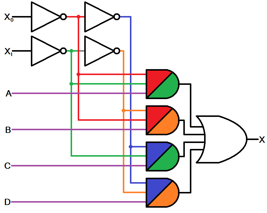
Multiplexer is a combinational logic circuit which allows only one input at a particular time to generate the output.
It uses a tree architecture with a recursive series of 2 : The truth table can easily be modified for muxes are most often used in digital circuits to transfer data elements from a memory array to data processing. We can easily understand the operation of the above circuit. The following figure shows the 4x1 multiplexer circuit diagram using and gates.
Bagikan Artikel ini
Belum ada Komentar untuk "Circuit Diagram Of 4 1 Multiplexer"

Belum ada Komentar untuk "Circuit Diagram Of 4 1 Multiplexer"
Posting Komentar