23+ Cmos Logic Diagram For Xor Gate Gif. Two input xor gate circuit diagram and stick diagram. A phase detector or phase comparator is a logic circuit that generates an analog output voltage signal which represents the difference in phase between two logic signal inputs.
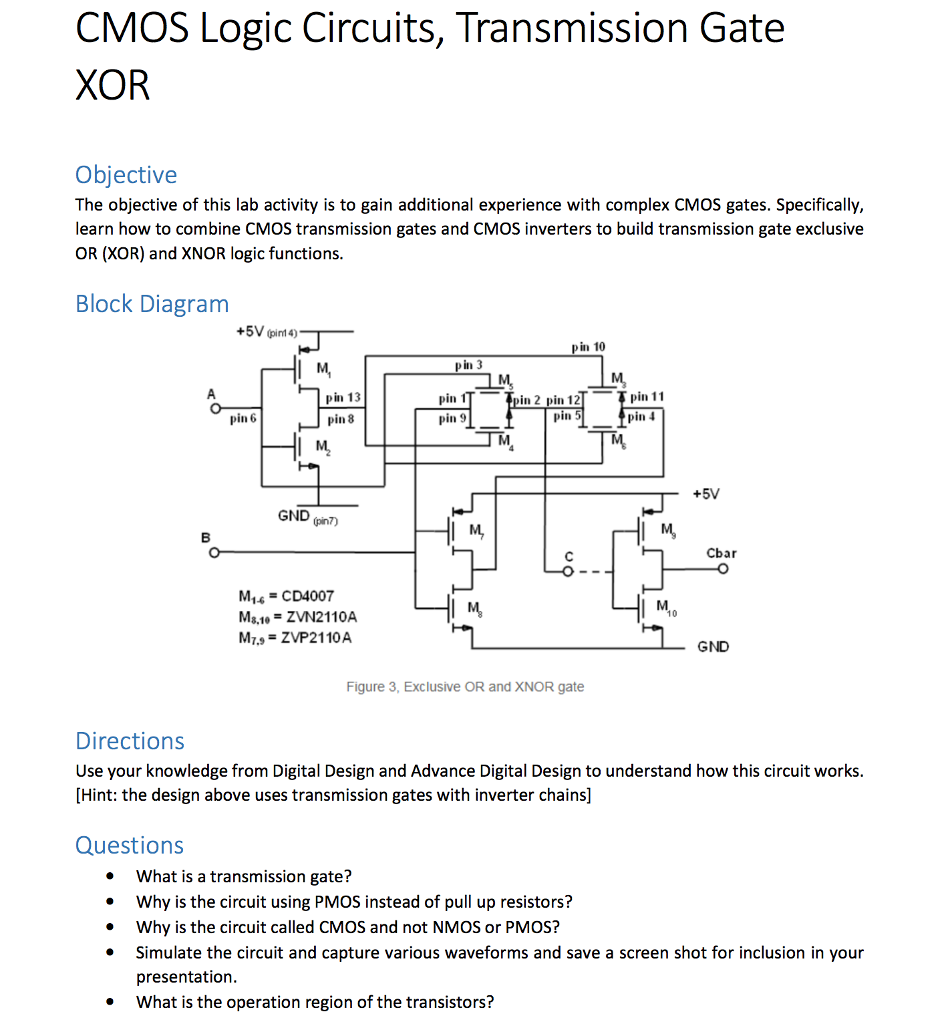
Solved: CMOS Logic Circuits, Transmission Gate XOR Objecti ... from d2vlcm61l7u1fs.cloudfront.net The xor gate is a digital logic gate that implements an exclusive or; Detecting the phase relationship between signals. Any input 0, means corresponding output is 1.
The schematic diagram of the cmos nand cell.
Basic tutorial on creating a cmos xor gate schematic symbol and layout using cadence virtuoso. The xor gate is a digital logic gate that implements an exclusive or; Cmos logic gates this worksheet and all related les are licensed under the creative commons attribution license, version 1.0. This example shows a cmos xor gate.
Bagikan Artikel ini
Belum ada Komentar untuk "Cmos Logic Diagram For Xor Gate"

Belum ada Komentar untuk "Cmos Logic Diagram For Xor Gate"
Posting Komentar