37+ Circuit Diagram Of Xnor Gate Gif. I request if you help me in drawing circuit diagram with and gate. The xnor gate (sometimes enor, exnor or nxor and pronounced as exclusive nor) is a digital logic gate whose function is the logical complement of the exclusive or (xor) gate.
Logic Gate: Types including Circuit Diagram, Symbols and Uses from www.watelectronics.com Read this guide to create your own logic gate easily with edraw max! The circuit would be possible with vanilla redstone mechanics. Each of the symbols below can be used to represent an xnor gate.
Nor gate usually has 2 input and 1 output.
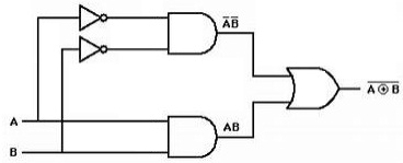
The pinout and connection diagram of the 74hc266n ic is shown below The first stage of the circuit is supposedly logic splitting to produce complementary copies of the input signals. First figure shows the circuit diagram of xnor gate, it uses npn transistor. In boolean expression, the term xnor is represented by symbol (⊙) and the boolean expression is represented as y = a ⊙ b.
Bagikan Artikel ini
Belum ada Komentar untuk "Circuit Diagram Of Xnor Gate"

Belum ada Komentar untuk "Circuit Diagram Of Xnor Gate"
Posting Komentar