Circuit Diagram Zener Diode Voltage Regulator
Get Circuit Diagram Zener Diode Voltage Regulator Background. A zener diode is a special type of diode designed to reliably allow current to flow backwards when a certain set reverse voltage, known as the zener voltage, is reached. It only requires a single resistor for configuring a zener diode based voltage regulator stage, and can be quickly added to any circuit for the intended results.
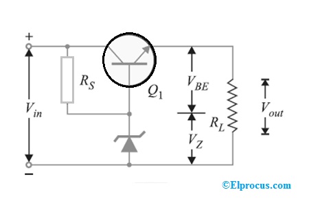
How a zener diode voltage regulator circuit works.
2.2.3 shows a block diagram of a series regulator circuit with error amplification. Of pins:2pins american power devices inc. The zener diode voltage regulator is based on a particular characteristic of zener diodes. The zener diode then acts to regulate the output.

Belum ada Komentar untuk "Circuit Diagram Zener Diode Voltage Regulator"
Posting Komentar